+86 13794985240


Choosing an Arm Cylinder in 2026 is not simply a matter of matching a part number to a machine. The cylinder must deliver the force, stroke, and control the application requires, while fitting the arm’s geometry and mounting points. A mismatch can cause sluggish movement, uneven loading, or premature wear. Small details matter.
Start with the machine’s operating pressure, required push and pull forces, stroke length, and available installation space. Then consider rod diameter, pin dimensions, hose routing, and how the arm moves through its full working range. A tape measure and the equipment manual can prevent an expensive ordering mistake. Check twice.
Real working conditions matter as much as catalog specifications. An excavator handling wet soil, for example, may face shock loads and contamination that a clean workshop test does not reveal. Seal material, corrosion protection, duty cycle, and service access should all be part of the decision. No chart captures every machine’s real-world load.
In this guide, we’ll explain how to compare cylinder specifications, verify compatibility, and assess build quality without relying on price alone. Manufacturer drawings and pressure ratings provide useful evidence, but confirm them against the machine’s documentation and actual setup. If a measurement or load estimate remains uncertain, pause and verify it with a qualified supplier or technician. That extra check may feel tedious; it is usually cheaper than a poor fit.
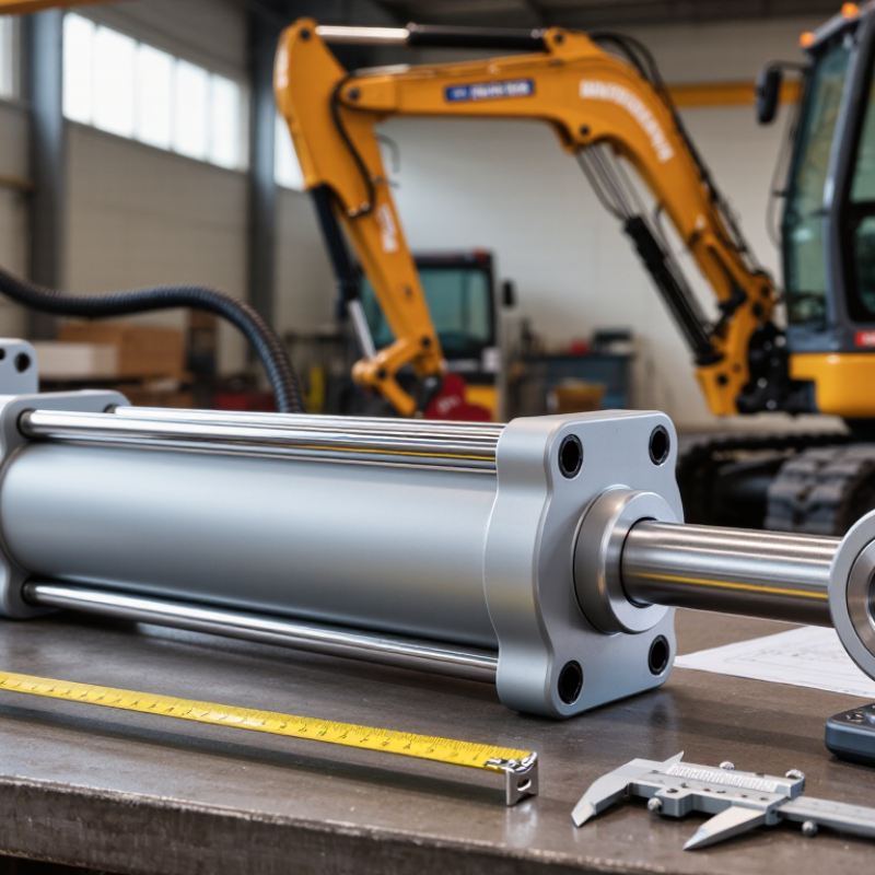
An arm cylinder converts hydraulic pressure into the controlled movement of an equipment arm. It helps lift, curl, and position a load, but its work is shaped by the machine’s geometry. A cylinder that looks adequate on paper may struggle when the arm is extended or the load sits far from the pivot. Check the equipment manual for rated pressure, mounting dimensions, and approved cylinder specifications. Then consider the actual tasks: steady digging, frequent lifting, or precise positioning each place different demands on the cylinder.
Operating conditions matter just as much as force. Record typical and peak loads, working pressure, stroke length, and available space between mounting points. Note whether the machine works in cold mornings, dusty sites, or wet conditions. These factors can affect seals, lubrication, corrosion, and service intervals. Inspect pins and bushings too; wear there can cause side loading, which may damage a cylinder not designed to absorb it. Measurements taken with the arm in several positions are more useful than a single estimate. Still, field measurements can be imperfect, so verify them before ordering.
Tips: Compare cylinder dimensions and load ratings with the machine manufacturer’s specifications. Allow for peak loads, not just normal work. Small details matter. If movement is jerky or leaks appear, stop and have a qualified technician inspect the system before selecting a replacement.
Choosing an arm cylinder in 2026 starts with the machine’s real geometry, not a catalog bore. Measure pin-to-pin length at full retraction and extension, then check the cylinder’s path through the entire swing. Small angles matter. Near a linkage’s dead-center position, the cylinder may need far more force to move the same load.
Estimate required force from pressure multiplied by piston area, then account for the rod-side annular area during retraction. Include attachment weight, material impact, friction, and pressure losses; a static load alone can understate demand. Check rod strength at full extension, especially on long-stroke cylinders. ISO 6020-2:2015 specifies dimensions for a medium-series cylinder range at 16 MPa, but that standard does not confirm a cylinder suits your machine’s mounting or duty cycle.
Grand View Research’s 2024 hydraulic cylinder market report valued the global market at about US$14.6 billion in 2023. That scale reflects varied applications, not interchangeable sizing. Compare the calculated load with the machine’s pressure limits and the cylinder’s rated force, then verify pin diameters, joint clearance, and hose routing on the actual linkage. A drawing can miss flex, wear, or a slightly bent pin. Recheck measurements in the field; I would not treat one neat calculation as proof of safe fit.
How to Choose an Arm Cylinder in 2026?
Comparing Bore, Rod, Stroke, and Mounting Configurations
Choosing an arm cylinder starts with the force and motion your machine actually needs. Bore size sets the piston area and strongly affects extension force at a given hydraulic pressure. Retraction force is lower because the rod takes up part of that area. A larger bore may solve a force problem, but it can also demand more oil flow and slow the cycle. Rod diameter matters too. A long, slender rod is more vulnerable to buckling under compression, especially when the arm is near full extension. Side loads can cause wear; cylinders are not designed to correct poor linkage alignment.
Tips: Check the machine’s working pressure, available flow, load, and duty cycle. Measure pin diameters and the closed and extended lengths. A few millimeters matter.
Stroke must cover the arm’s required travel without forcing the cylinder to become the mechanical stop. Compare clevis, pin, trunnion, or flange mounts with the existing frame, and check that the pins align through the full movement. On a compact excavator, a cylinder that fits when parked may bind as the boom swings. That detail is easy to miss. A catalog match can look convincing, yet still be wrong in the machine. Verify dimensions and clearances against the actual linkage before ordering.
How to read the chart: Larger bores provide more theoretical force. Retraction force is lower because the rod reduces the effective piston area. Values are calculated at a constant 210 bar using representative bore/rod pairs; actual cylinder ratings and delivered force depend on the design, pressure losses, and operating conditions.
Choosing the other dimensions: Select a rod diameter to handle compressive loads and buckling risk, especially on long strokes. Stroke sets the required travel but does not change ideal force at a given bore and pressure. Choose a mounting style—such as clevis or trunnion for pivoting motion, or a flange or foot mount for rigid support—that matches the load path and allows proper alignment.
Evaluating Pressure Ratings, Materials, Seals, and Service Life
A cylinder’s pressure rating must suit the machine’s working pressure and foreseeable spikes. Check the system’s relief setting, load direction, and duty cycle, not just its usual gauge reading. A cylinder operating near its limit may wear faster, even when it seems adequate during a brief test. Leave a sensible margin, and confirm sizing with the equipment manufacturer or a qualified hydraulic engineer.
Material choice depends on the environment. A plated rod may resist corrosion, while a suitable barrel and sturdy mounting points help handle repeated loads. Look closely at clevis pins and rod surfaces; scratches can damage seals. Small details matter. Seal material must match the hydraulic fluid, temperature range, and exposure to dust or moisture. A good wiper helps keep grit out, but it cannot compensate for poor maintenance.
Service life also depends on alignment and side loading. If the arm pushes at an angle, the rod and seals may wear unevenly. Inspect for oil film, scoring, loose mounts, and slower movement. Keep a simple record of cycles and repairs. It is not perfect, but it can reveal a pattern before failure interrupts work. Actual life varies with installation, load, and maintenance.
Choosing an arm cylinder starts with matching its movement to the machine. Measure the required stroke, pin diameter, mounting width, and available clearance. Check the retracted and extended lengths against the arm’s full travel. A cylinder that fits on the bench may still bind at the far end.
Check the machine manual for operating pressure, fluid type, and load limits. Small differences matter. “Close enough” is not a safe specification. Before inspection or removal, lower the arm, support it securely, and release stored pressure according to the service procedure. Never rely on hydraulic pressure to hold a raised load. Examine the rod for scoring, the barrel for dents, and the mounts for cracks or unusual wear. If dimensions or pressure ratings are unclear, ask a qualified technician to verify them.
Maintenance needs depend on duty cycle, dust, moisture, and temperature. Wipe the exposed rod with a clean cloth, look for fresh oil around seals, and listen for uneven movement. Follow the equipment maker’s inspection intervals; harsh conditions may call for more frequent checks. Keep fluid clean and use only the specified type. A leak can look minor at first. It may not stay that way. Records help, though they cannot replace a careful inspection.
| Selection Dimension | What to Check | Practical Guidance | Before Installation or Purchase |
|---|---|---|---|
| Application and machine compatibility | Machine model, arm geometry, duty cycle, and the cylinder’s function in the hydraulic circuit. | Choose a cylinder intended for the machine and application. Similar-looking cylinders may differ in stroke, force, mounting, port location, or operating limits. | Compare the machine service information and the existing cylinder identification or documented specifications. Do not select by appearance alone. |
| Stroke and closed length | Required travel, pin-center length when retracted, and available clearance through the full arm movement. | The stroke must provide the required movement without causing the cylinder to bottom out or the machine linkage to exceed its intended travel. | Confirm measurements and check clearance at both ends of travel, including hoses, guards, and nearby structure. |
| Bore, rod, and required force | Piston bore, rod diameter, system pressure, and the load imposed by the machine’s linkage. | For an idealized cylinder, extension force is pressure multiplied by piston area; retraction force uses the smaller annular area after subtracting rod area. Actual usable force also depends on the linkage, friction, and operating conditions. | Use the machine’s design data or a qualified hydraulic calculation. Do not infer safe lifting capacity from cylinder dimensions alone. |
| Pressure and hydraulic connections | Maximum working pressure, pressure spikes, port thread or flange type, port size, and connection orientation. | The cylinder’s rated working pressure must be suitable for the system. Connections must match the circuit and hoses; adapters should not be used to compensate for an unverified specification. | Verify the machine’s pressure limits and the cylinder documentation. Check connection type, sealing method, and hose routing before pressurizing. |
| Mounting and pin alignment | Mount style, pin diameter, bearing width, pin-center spacing, and alignment through the full operating arc. | Mounting dimensions and articulation must match the machine. Misalignment can cause side loading, accelerated seal or bearing wear, and damage to the rod or cylinder. | Inspect pins, bushings, retainers, and mounting ears for wear or damage. Confirm that the cylinder pivots freely after installation. |
| Speed and flow | Required arm movement speed, available hydraulic flow, and circuit restrictions. | In general, cylinder speed depends on supplied flow and the effective piston area. A larger cylinder is not automatically a suitable replacement: it can change speed, force, and system behavior. | Check the machine’s flow specifications and control-valve capacity. Confirm that the replacement is approved for the intended circuit. |
| Rod strength and side loading | Rod diameter, unsupported length, alignment, and whether the design subjects the cylinder to bending or side force. | Hydraulic cylinders are primarily intended to apply force along their axis. Side loading and poor alignment can shorten service life and may cause failure. | Check linkage condition and alignment. Investigate recurring rod damage or uneven wear rather than replacing the cylinder without addressing the cause. |
| Safety and load control | Machine-specific safety requirements, pressure limits, load-holding arrangements, and safe servicing procedures. | Hydraulic systems should be designed and maintained in accordance with applicable requirements, such as ISO 4413. A cylinder alone does not guarantee that a suspended or raised load is safely held. | Follow the machine manufacturer’s procedures. Lower or mechanically support the attachment, relieve stored pressure as directed, and keep personnel clear of moving parts before service. |
| Fluid, seals, and operating environment | Specified hydraulic-fluid type and cleanliness, temperature range, seal material, dust, moisture, and exposure to corrosion. | Use fluid and seals compatible with the machine and cylinder documentation. Contamination, unsuitable fluid, and damaged rod surfaces can lead to leakage and premature wear. | Check fluid condition and filtration requirements. Inspect the exposed rod for scoring, corrosion, or contamination and keep the rod and connection areas clean. |
| Inspection and maintenance | Leakage, loose or worn pins, abnormal movement, noise, rod damage, and changes in machine performance. | Inspection intervals should follow the machine’s service schedule and be adjusted for operating conditions. Repair or replacement decisions should be based on documented limits and qualified assessment. | Record inspections and repairs. Do not search for leaks with a hand; high-pressure hydraulic fluid can penetrate skin and requires urgent medical attention. |
| Standards and documentation | Applicable cylinder design or mounting standards, machine documentation, and traceable pressure and dimensional specifications. | Standards such as ISO 6020-2 and ISO 6022 cover dimensions for certain series of hydraulic cylinders; they do not make every cylinder interchangeable or establish suitability for every machine. | Confirm the relevant standard, series, dimensions, and operating limits from the technical documentation before treating a cylinder as a compatible substitute. |
| Final compatibility decision | All critical dimensions, ratings, connections, mounting details, and safety requirements. | Approve a replacement only when its specifications are verified against the machine requirements. If specifications are missing or conflict, consult the machine manufacturer or a qualified hydraulic professional. | Keep the approved specifications and installation records with the machine’s maintenance documentation. |