How to Choose the Right Arm Cylinder for Your Machine
Choosing the right Arm Cylinder starts with understanding the work your machine actually performs. A loader lifting a bucket faces different forces from a press holding a steady load. Even similar machines may need different cylinder sizes, strokes, or mounting arrangements.
The nameplate is a useful starting point, not the whole answer. Check the required force, operating pressure, stroke length, available space, and connection points. A mismatch can cause slow movement, poor alignment, or unnecessary strain on related components. Looks simple. It often isn’t.
This guide explains how to compare cylinder specifications with real operating conditions. It also considers duty cycle, fluid compatibility, temperature, and exposure to dust or moisture. These details matter in a workshop, on a farm, or at a busy jobsite. A cylinder that works well in one setting may wear quickly in another.
Use the machine manual and the cylinder manufacturer’s data to confirm important measurements. When loads or operating conditions are uncertain, a qualified technician can help verify the selection. A tidy specification sheet can still miss what happens during a rough shift. That is worth reflecting on.
There is no single perfect choice for every machine. The aim is a cylinder that meets the required performance without being poorly matched to the equipment. Careful comparison can help you make a safer, more reliable decision and avoid preventable downtime.
Define the Arm-Cylinder Load, Duty Cycle, and Safety Limits Under ISO 4413
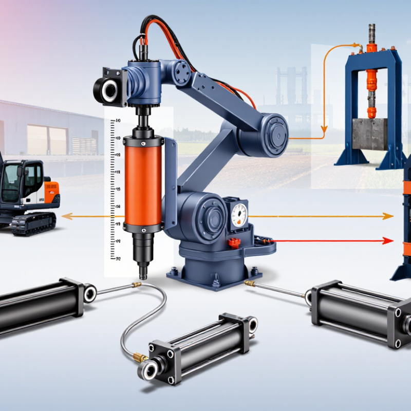
An arm cylinder must be sized for the load at its worst geometry, not just the machine’s nominal payload. Calculate force from pressure and piston area, then account for linkage angle, friction, and backpressure. For example, a 100 mm bore at 160 bar produces about 126 kN of ideal extension force; the usable force will be lower. ISO 4413:2010 requires hydraulic systems to address foreseeable operating conditions and hazards, but it does not prescribe one universal cylinder safety factor or duty cycle. Measure the actual load profile.
Duty cycle means more than cycles per hour. Record stroke, cycle time, pauses, starts, and pressure peaks across a representative shift. A short pressure trace can reveal shock loads that a steady-state calculation misses. The weak point? A single “typical” shift may hide seasonal or jam-clearing loads. Check the cylinder’s rated pressure and fatigue limits against measured peaks, including relief-valve settings. ISO 10100:2020 provides acceptance-test methods for hydraulic cylinders; use test results and supplier ratings to verify selection.
Safety limits matter during faults and maintenance, too. Follow ISO 4413’s system-level safety principles: control pressure, prevent unintended movement, and provide safe ways to isolate and release stored energy. Support the arm mechanically before anyone enters its danger zone; trapped oil can still hold a load. Small details matter. Keep the calculations, pressure logs, and test conditions together, and revisit them when the machine’s tooling or work cycle changes.
| How to Choose the Right Arm Cylinder for Your Machine — Define the Arm-Cylinder Load, Duty Cycle, and Safety Limits Under ISO 4413 |
| Illustrative Machine Duty |
Peak Load at Arm |
Linkage Ratio at Worst Position |
Duty Cycle |
Example Design Allowance |
Calculated Cylinder Thrust |
Example Cylinder Bore |
Extension Force at 16 MPa |
Checks Before Selection |
| Compact positioning arm |
5 kN |
0.80 |
120 cycles/hour; approximately 20% time under pressure |
1.30 |
8.13 kN |
32 mm |
12.87 kN |
Check peak acceleration, rod strength, pin loads, stroke, and whether the load can cause uncontrolled movement. |
| General-purpose handling arm |
12 kN |
0.60 |
60 cycles/hour; approximately 35% time under pressure |
1.50 |
30.00 kN |
50 mm |
31.42 kN |
Verify force throughout the full arm travel, including the least favorable linkage position; check cushioning and heat generation. |
| Heavy articulated arm |
25 kN |
0.75 |
30 cycles/hour; approximately 50% time under pressure |
1.40 |
46.67 kN |
63 mm |
49.88 kN |
Check extended-rod buckling, fatigue life, mount and pin capacity, shock loads, and the required load-holding method. |
|
Calculation basis: The linkage ratio is the cylinder’s effective moment arm divided by the load’s effective moment arm at the stated worst position. Estimated cylinder thrust = peak arm load ÷ linkage ratio × example design allowance. Extension force is calculated as pressure × piston area, using an illustrative working pressure of 16 MPa. Values are examples for preliminary comparison, not final component ratings.
|
|
ISO 4413 safety considerations: ISO 4413:2010 sets general rules and safety requirements for hydraulic fluid power systems and components; it does not prescribe a universal cylinder-sizing allowance. Confirm system pressure limits and protection against pressure exceeding component ratings, unintended movement, and hazardous load descent. Where a suspended or otherwise hazardous load must be held, assess suitable load-holding and isolation measures. Final selection also requires checking dynamic loads, rod buckling, side loading, mounting strength, stroke, fluid and temperature conditions, and the machine’s risk assessment.
|
Calculate Bore and Rod-Side Force Using F = P × A at 20–35 MPa
Choosing an arm cylinder starts with the force needed at the machine, not a guess based on outside dimensions. Use F = P × A, with pressure in MPa and area in mm²; because 1 MPa equals 1 N/mm², the result is in newtons. Check the machine’s actual operating pressure. Systems may run between 20 and 35 MPa, but the maximum rating is not always the pressure available during a working cycle.
For example, an 80 mm bore has a piston area of about 5,027 mm². At 25 MPa, its theoretical extension force is roughly 126 kN. Retraction force is lower because the rod takes up part of the piston area. With a 45 mm rod, the annular area is about 3,436 mm², giving roughly 86 kN at the same pressure. A useful detail. These are ideal figures, before friction, pressure losses, or seal drag.
Compare both forces with the load at the cylinder pin, accounting for linkage angles and the hardest point in the stroke. A tidy calculation can still miss a side load. Check rod diameter, stroke length, mounting alignment, and the machine’s duty cycle; a long, slender rod may need more attention to buckling than bore size alone. Real measurements can be imperfect, so verify pressure under load and leave a suitable design margin.
Set Stroke and Speed from Arm Geometry and the Flow Relation Q = A × v
How to Choose the Right Arm Cylinder for Your Machine
Set Stroke and Speed from Arm Geometry and the Flow Relation Q = A × v
An arm’s reach is not the cylinder’s required stroke. Measure the pin-to-pin distance at both ends of the intended motion, then subtract the shorter distance from the longer one. Check the full travel path, not just the endpoints; a linkage can approach a difficult angle midway through its movement. Sketch the pivot points and verify that the cylinder will not hit a frame or pass through a dead-center position.
Tips: For speed, use Q = A × v. Here, Q is flow, A is the cylinder’s effective area, and v is piston speed. Rearranged, v = Q ÷ A. A 50 mm bore has about 0.00196 m² of piston area, so 10 L/min gives roughly 0.085 m/s on extension, before losses. Retraction is faster at the same flow because the rod reduces effective area.
Treat that estimate as a starting point. Real speed may fall under load, with long hoses, or through restrictive valves. Compare the calculated cycle time with the machine’s actual task, and check available pump flow during simultaneous movements. I would also review load and mounting angles before finalizing the bore; it is easy to size for speed and overlook force. Leave room to adjust. A small mismatch often appears only during the first loaded test.
Size the Piston Rod for Buckling with a 3× Safety Factor
How to Choose the Right Arm Cylinder for Your Machine
A cylinder’s force rating does not tell you whether its piston rod will stay straight under compression. Buckling risk rises when the rod is extended, slender, or poorly aligned. Measure the unsupported rod length at the machine’s longest working stroke. Include the mounting arrangement, since a pinned end and a rigidly supported end behave differently.
Size the rod so its calculated buckling capacity is at least three times the maximum compressive load. In practical terms, divide the estimated buckling limit by the load the rod must carry; the result should be 3 or greater. Use the correct effective length for the end supports, and confirm the material and rod diameter used in the calculation. A small change in diameter can make a substantial difference. Small details matter.
Use the highest credible load, not just the cylinder’s steady push. Account for shock, deceleration, and any side force that could bend the rod. Check the full stroke. On a machine, a bracket that looks square can still introduce slight misalignment. A neat calculation may miss that. Treat the result as a design check, then have a qualified engineer review unusual mounting conditions or changing loads before selecting the cylinder.
Check Mounting Dimensions Against ISO 6020-2 and Match Seals to the Fluid
How to Choose the Right Arm Cylinder for Your Machine
Check Mounting Dimensions Against ISO 6020-2 and Match Seals to the Fluid
A cylinder can fit the space and still bind under load. Compare the mounting style, pin diameter, center-to-center length, and port location with the machine drawing. ISO 6020-2:2015 specifies dimensions for a compact hydraulic cylinder series rated at 16 MPa (160 bar). Treat that as a reference, not proof of a direct replacement. Measure the installed unit, including pin-to-pin length at both stroke limits. A few millimeters can change linkage geometry.
Seal choice depends on the actual fluid, temperature, and additives. Mineral oil, water-glycol, and phosphate ester fluids do not suit every elastomer. Check the fluid supplier’s compatibility data, then verify the seal compound’s temperature range. ASTM D471 provides a test method for measuring how rubber changes after liquid exposure. Ask for test results in the intended fluid; generic “oil resistant” wording is not enough. Small detail. Big consequence.
Inspect the old seal for hardening, swelling, or a flattened lip, but do not assume it tells the whole story. Contamination and heat can leave similar marks. Confirm rod surface condition, too: a scratch you can catch with a fingernail may damage a new seal quickly. If the fluid specification is unclear, pause the order and identify it first. That extra check may feel slow. It is usually cheaper than an early leak and another teardown.

 +86 13794985240
 CONTACT NUMBER
 CONTACT NUMBER