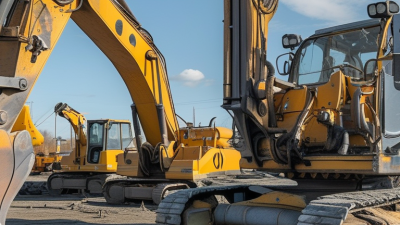
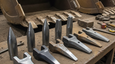
7 Tips for Choosing the Right Arm Cylinder
Choosing the right Arm Cylinder begins with more than matching a part number. The cylinder must fit the machine’s geometry, carry the working load, and perform reliably through repeated cycles. A mismatch can show up as slow movement, uneven force, excess heat, or premature seal wear. Small details matter. Measure the pin-to-pin length at both stroke limits. Check the bore, rod diameter, mounting style, port location, and available clearance. Then compare the operating pressure and duty cycle with the manufacturer’s specifications.
A practical reminder for this guide is: “Choose for the real load and motion, not just the dimensions on a drawing.” No source material was provided to verify a named expert’s quotation, so this line is original editorial wording, not a quote attributed to an industry specialist. That distinction matters when technical advice needs to be trustworthy. The seven tips ahead will help you assess fit, force, stroke, materials, seals, and supplier documentation. They also highlight a common oversight: a cylinder can appear suitable on paper yet perform poorly when side loading or harsh operating conditions are ignored. Field checks help. Record actual measurements, note how the equipment is used, and confirm uncertain details with the cylinder manufacturer. A careful selection takes time. It can prevent avoidable downtime and make the machine’s movement more predictable.
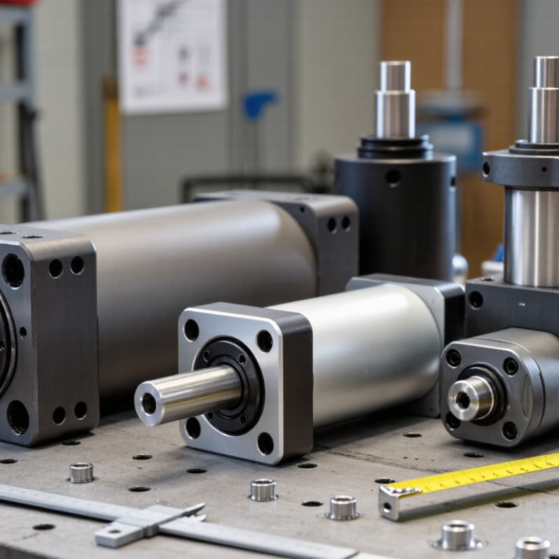
Define Arm Loads and Required Cylinder Force with F = Pressure × Area
Choosing an arm cylinder starts with the load at the arm, not just the cylinder. Estimate the load’s weight and distance from the pivot, then account for the arm’s angle and linkage geometry. A cylinder pushing close to the pivot may need far more force than one acting farther out. Small details matter.
Use F = pressure × area to estimate cylinder force. Here, area means the piston’s effective area, and pressure should reflect what reaches the cylinder under working conditions—not only the pump’s rated maximum. For a retracting stroke, the rod reduces the effective area, so available force is lower. Compare required force with available force throughout the arm’s motion, allowing for friction, acceleration, and pressure losses. A neat calculation can still miss a tight spot in the linkage. Check it.
Tip: Measure real operating pressure where practical, and verify the cylinder’s bore and rod dimensions against the calculation. Include a sensible margin, but don’t use an oversized cylinder to hide uncertain load estimates; it can strain pins, mounts, and the arm. Check mounting alignment and rod stability, especially near full extension. If the load or geometry is uncertain, test cautiously and review the assumptions before final sizing.
Match Bore and Pressure to ISO 6022’s 25 MPa Cylinder Series
ISO 6022:2018 specifies mounting dimensions for single-rod cylinders in the 25 MPa (250 bar) series. It does not certify that every circuit can safely operate at that pressure. Check the cylinder rating, seals, ports, hoses, valves, and relief setting against actual duty. For a rough bore check, a 50 mm piston has an area of 0.00196 m². At 25 MPa, its ideal extension force is about 49 kN. Real force falls with friction and pressure losses. That matters.
Calculate peak load, not average load, and use the correct piston area. Retraction acts on annular area, so rod volume reduces available force. Choose a bore that meets demand at available pressure, then check rod buckling, stroke, alignment, side load, and cycle rate. Long strokes can make a slender rod vulnerable even when bore force looks adequate. ISO 4413:2010 provides system-level safety requirements for hydraulic components and circuits. A gauge near the cylinder reveals losses; a pump gauge alone may mislead. Field measurements are imperfect. Recheck them.
7 Tips for Choosing the Right Arm Cylinder - Match Bore and Pressure to ISO 6022’s 25 MPa Cylinder Series
| Tip |
What to check |
Useful data and selection guidance |
| 1. Confirm the pressure series |
Check that the cylinder is specified for the system’s maximum operating and peak pressure. |
ISO 6022 covers a 25 MPa (250 bar) hydraulic cylinder series. Do not treat this series rating as permission to exceed the cylinder’s stated limits; account for pressure spikes and the complete circuit rating. |
| 2. Size the bore for force |
Compare the required pushing force with the theoretical extension force available at the actual working pressure. |
Common ISO 6022 nominal bores and theoretical extension forces at 25 MPa:
50 mm: 49.1 kN; 63 mm: 77.9 kN; 80 mm: 125.7 kN; 100 mm: 196.3 kN; 125 mm: 306.8 kN; 160 mm: 502.7 kN; 200 mm: 785.4 kN; 250 mm: 1,227.2 kN; 320 mm: 2,010.6 kN.
Values use F = p × πD²/4 and are theoretical; friction and pressure losses reduce delivered force.
|
| 3. Check return force and rod size |
Make sure the cylinder can pull the load as well as push it. |
Retraction force is calculated on the annular area: F = p × π(D² − d²)/4, where D is bore and d is rod diameter. Use the selected cylinder’s actual rod diameter and working pressure. |
| 4. Match stroke to the movement |
Measure the required travel between fully retracted and fully extended positions. |
Specify stroke in millimetres and confirm the available installation length at both end positions. Long strokes may require additional checks for rod buckling and lateral loading. |
| 5. Check rod stability and side load |
Review the force direction, stroke, mounting arrangement, and unsupported rod length. |
Cylinder rods are designed primarily for axial loading. Use the cylinder manufacturer’s buckling data for the actual stroke and end conditions, and guide the load separately where side forces are present. |
| 6. Verify mounting and alignment |
Match the cylinder mounting style and connection dimensions to the machine. |
Check the applicable ISO 6022 mounting arrangement, pin or flange dimensions, and available clearance. Keep the cylinder aligned with the load throughout its stroke to avoid unintended rod and seal wear. |
| 7. Specify cushioning and service conditions |
Consider end-of-stroke speed, moving mass, cycle rate, fluid, and operating temperature. |
End cushioning can help decelerate a load near the end of travel, but it must be selected for the application’s energy and speed. Confirm seal and fluid compatibility and follow the cylinder’s published limits. |
Choose Stroke and Mounting Dimensions for the Arm’s Full Range of Motion
The cylinder’s stroke must match the arm’s full movement, not just its visible reach. Measure the pin-to-pin distance at both travel limits, with the arm fully retracted and extended. The difference is the minimum working stroke; allow extra travel only if the design safely accommodates it. A few millimeters can matter. Check the entire path for interference with the frame, hoses, and nearby joints.
Tip: Sketch the arm’s side profile at its motion limits. Record both pin-center distances, then compare the result with the cylinder’s closed and extended lengths. ISO 6020-2:2015 provides dimensional tables for compact hydraulic cylinders in the 16 MPa (160 bar) series. Use those tables to check standard mounting dimensions, but verify the actual clevis, pin, and available clearance on your arm.
Mounting points set the cylinder’s leverage. A cylinder that fits at rest may bind near full extension or produce poor force at an awkward angle. Check the geometry across the complete arc, especially where the cylinder and arm nearly align. That position can sharply reduce useful turning force. One easy-to-miss detail: include pin hardware and joint movement in your measurements. Recheck the layout with a scale drawing or CAD model; assumptions about clearance are often optimistic.
Check Rod Buckling, Side Loads, and System Safety Under ISO 4413
An arm cylinder may see more than axial force. A bucket snag or offset load can push sideways on the rod. ISO 4413:2010 requires hydraulic systems to address foreseeable hazards, including pressure-related risks. It does not provide one universal side-load allowance for every cylinder. Check the cylinder maker’s load data and assess the actual linkage geometry.
Rod buckling deserves a calculation, not a guess. As a screening example, Euler’s formula gives an ideal buckling load of about 40 kN for a 25 mm steel rod with a 1 m pinned length, assuming an elastic modulus of 210 GPa. Real capacity can be lower. End conditions, rod extension, misalignment, and shock all matter. Leave a suitable design margin, and check the cylinder at its longest working extension. Small offsets add up.
Side loads can also wear seals and guide bushings before obvious bending appears. Inspect for uneven rod scoring, leakage, and looseness at the pivot. ISO 4413 calls for protection against excessive pressure and safe control of stored energy; provide suitable relief and isolation measures, then verify them during maintenance. A tidy drawing can still hide a risky load path. I would revisit the calculation after any attachment change.
7 Tips for Choosing the Right Arm Cylinder
Compare theoretical cylinder force, then check rod buckling, side loads, and system safety under ISO 4413.
Example theoretical forces at 6 MPa (60 bar), calculated from piston area; retraction values account for the rod area. Assumed rod diameters are 18, 22, 28, 35, and 45 mm for the respective bores. Actual force will be lower due to friction and system losses. These figures do not establish a safe working load: verify rod buckling for the cylinder’s mounting and stroke, prevent side loads with suitable guidance, and assess the complete hydraulic system against ISO 4413.

 +86 13794985240
 CONTACT NUMBER
 CONTACT NUMBER