Leave Your Message

How to Choose a Frame Support Bracket in 2026?

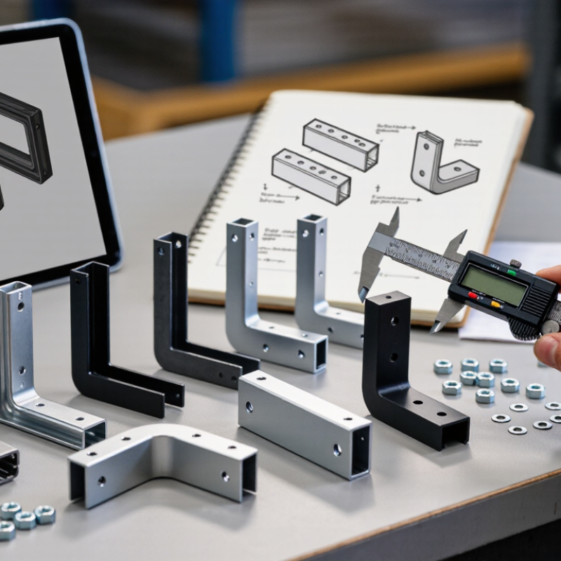
Choosing a Frame Support Bracket in 2026 is not a matter of picking the thickest piece of steel. The right choice depends on the frame, the load, the fixing surface, and the conditions around the installation. A bracket that looks sturdy on a screen may flex when a door closes repeatedly or when equipment vibrates nearby. Small parts matter.

Before comparing products, identify what the bracket must support and how that force reaches the wall, floor, or frame. Check dimensions, material, finish, hole spacing, and the manufacturer’s stated load capacity. A mismatch of only a few millimeters can leave a fastener poorly seated. Moisture, temperature changes, and frequent movement can also affect long-term performance.

Engineering author Henry Petroski offers a useful general reminder in the title of his book, “To Engineer Is Human.” This is not a frame-bracket-specific quotation, and no verified quotation from a bracket-industry expert was provided. A reliable guide should not invent one. The same careful thinking applies here: compare documented specifications, installation requirements, and the actual support conditions before choosing. Fit comes first.

This article will explain how to assess bracket style, material, load rating, and compatibility in 2026. It will also point out where product descriptions can leave important questions unanswered. A bracket is only one part of a support system. The frame, fasteners, and mounting surface matter too.
How to Choose a Frame Support Bracket in 2026?

Define Bracket Loads and Load Combinations Using ASCE 7

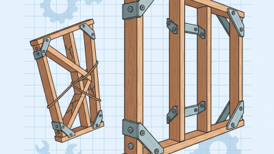
A reliable frame support bracket begins with a clear load path: from the supported frame, through the bracket and fasteners, into the structure. Identify dead load, live load, and relevant environmental loads, such as wind, snow, or seismic forces. Small details matter. A few millimeters of eccentricity can increase bracket bending and fastener tension.

Use the ASCE 7 edition adopted for the project, not simply the newest edition available in 2026. Determine applicable load combinations and keep strength-design or allowable-stress-design procedures consistent. Include direction and uplift where relevant; a vertical load check alone may miss wind suction or lateral force. A neat spreadsheet can still hide a bad assumption. Verify tributary area, support spacing, and whether loads act simultaneously. Then check bracket yielding, deflection, fastener capacity, and the supporting material under the governing combinations. Field conditions may differ from drawings, so confirm dimensions and substrate before final selection. Document assumptions and have a qualified structural professional review project-specific calculations.
Compare Steel Grades: ASTM A36 (250 MPa) and A572 Grade 50 (345 MPa)

How to Choose a Frame Support Bracket in 2026?

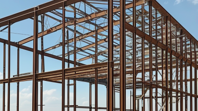
For a frame support bracket, steel grade affects strength, but it does not determine capacity alone. ASTM A36/A36M specifies a minimum yield strength of 250 MPa for common thickness ranges. ASTM A572/A572M Grade 50 specifies 345 MPa. That is roughly 38% higher yield strength. The difference can matter when a bracket carries concentrated loads or must fit into a tight space. Check the specified product thickness, though; minimum properties can vary by product form and thickness. The ASTM standards are the primary references for these grade requirements.

Higher yield strength is not a free pass to make every bracket thinner. AISC’s Steel Construction Manual treats member strength, stability, and connection design as separate checks. A thin bracket may buckle, bend near a bolt hole, or tear around a weld before the steel reaches its stated yield strength. Look closely at the load path: a shelf bracket, for example, may see a pulling force at its upper fastener and compression at its wall contact. Grade 50 can help where strength governs, while A36 may suit a robust, easily fabricated bracket. Fit and fabrication matter. I’d verify the actual load, thickness, weld details, and corrosion protection before choosing; that extra check can feel tedious, but skipping it leaves a real blind spot.

How to Choose a Frame Support Bracket in 2026?

Specified Yield Strength: ASTM A36 vs. ASTM A572 Grade 50

Using the values shown, A572 Grade 50 has a specified yield strength of 345 MPa, compared with 250 MPa for A36—about 38% higher. Yield strength alone does not determine bracket capacity; also consider bracket geometry, steel thickness, loading, connections, applicable design codes, and the relevant product specification.

Select Anchors for Concrete Supports Using ACI 318 Design Rules

How to Choose a Frame Support Bracket in 2026?

A frame support bracket is only as reliable as its connection to the concrete. Under the locally adopted edition of ACI 318, anchor design is addressed in Chapter 17. Start with the loads: determine tension, shear, and any combined effects transferred through the bracket. Then check concrete strength, anchor diameter, embedment, spacing, and distance to slab edges. Small details matter. A bolt placed close to an edge can trigger concrete breakout even when the steel anchor itself looks ample.

Account for cracked concrete where conditions or design assumptions require it, and consider seismic demands when applicable. ACI 318 checks can include steel failure, concrete breakout, pullout, side-face blowout, and pryout. The weakest mode governs. For a bracket carrying a heavy frame, a simple sketch showing anchor locations and load direction can expose awkward spacing before drilling begins. Verify that the selected anchor has suitable qualification data and installation instructions; adhesive anchors also depend on hole cleaning, temperature, and cure time.

Field conditions deserve a second look. Concrete is not uniform. Check drawings and site information for slab thickness, reinforcement, and concealed services, and avoid cutting reinforcing steel without engineering review. Installation tolerances may shift an anchor nearer an edge than the calculation assumed. It is easy to overfocus on bracket capacity and undercheck the concrete beneath it. That mistake is worth revisiting. Have a qualified engineer confirm the design assumptions, applicable ACI 318 edition, and final anchor layout before installation.

How to Choose a Frame Support Bracket in 2026? - Select Anchors for Concrete Supports Using ACI 318 Design Rules

Use this screening table to identify an anchor type and the design checks needed for a frame support bracket. Anchor capacities, minimum dimensions, and installation requirements must be verified for the selected anchor using its current evaluation report and the ACI 318 edition adopted for the project. The table is guidance, not a substitute for project-specific engineering.

Selection factor Information to establish Anchor selection guidance ACI 318 design / verification
Bracket design actions Factored tension and shear at each anchor; eccentricity; load direction; applicable load combinations. Choose an anchor layout and type that can resist the calculated tension and shear, including their interaction where applicable. Determine actions using the governing structural design standard. Check anchor steel strength and applicable concrete failure modes under ACI 318 Chapter 17.
Concrete condition Normal-weight or lightweight concrete; specified compressive strength; cracked or uncracked assumption; member thickness and reinforcement layout. Use an anchor qualified for the actual concrete condition and strength. For safety-related design, do not assume uncracked concrete unless the code conditions for that assumption are satisfied. Use the applicable Chapter 17 provisions and qualified design data. Check concrete breakout and other relevant concrete failure modes.
Cast-in headed anchor New concrete construction; anchor position can be set before placement; embedment and reinforcement can be coordinated. Consider for planned installations where accurate setting and coordination with the reinforcing steel are practical. Check steel strength, concrete breakout, pullout where applicable, side-face blowout where applicable, and effects of spacing, edges, and member thickness.
Post-installed mechanical anchor Existing concrete; drilled-hole installation; access for drilling, cleaning, setting, and inspection. Select a mechanically installed anchor with a current qualification for the relevant concrete condition, load type, and installation orientation. Use qualification data and installation limits for the specific anchor. Check Chapter 17 strength requirements and the applicable installation and inspection provisions.
Post-installed adhesive anchor Existing concrete; hole diameter and depth; concrete temperature; installation orientation; service temperature and sustained-load conditions. Consider only a qualified adhesive-anchor system suitable for the actual conditions. Specify hole cleaning, adhesive dispensing, cure time, and installer requirements. Check the applicable Chapter 17 strength and service provisions, including bond-related strength and any sustained-tension requirements. Follow the qualification report and installation instructions.
Spacing and edge distance Anchor spacing, distance to concrete edges, bracket hole pattern, concrete member boundaries, and nearby openings. Lay out anchors to avoid conflicts and to meet the selected anchor’s published minimum spacing and edge-distance limits. Do not use one universal spacing value for all anchors. Account for edge and spacing effects in the applicable Chapter 17 calculations; reduced distances can reduce design strength and may affect installation feasibility.
Embedment and member thickness Required effective embedment, available concrete thickness, backside clearance, and reinforcement interference. Set embedment within the qualified product range and confirm the concrete member is thick enough for the installation and required failure checks. Use the effective embedment and geometry definitions applicable to the anchor type. Check concrete breakout and other governing limit states.
Seismic and other special conditions Seismic design category and demand where applicable; fatigue, vibration, fire exposure, corrosion, or aggressive environment. Choose an anchor specifically qualified for any required seismic or environmental condition, and specify compatible materials and protection. Apply the relevant Chapter 17 provisions and project code requirements. Verify that the anchor’s qualification covers the required condition.
Final design and installation record Anchor identification, design calculations, approved drawings, installation instructions, inspection requirements, and as-built location. Confirm the installed anchor, bracket geometry, and field conditions match the approved design; document deviations for engineering review. Have a qualified design professional verify the applicable code edition, strength checks, detailing, and inspection requirements for the project.

Important: ACI 318 anchor design is condition- and geometry-dependent. Do not treat generic anchor capacities, embedment depths, edge distances, or spacing values as design values; obtain them from the current qualification data for the selected anchor and verify them for the project.

Match Corrosion Protection to ISO 12944 Exposure Classes C1–CX

How to Choose a Frame Support Bracket in 2026?

Match Corrosion Protection to ISO 12944 Exposure Classes C1–CX

A frame support bracket can look sound while corrosion starts beneath its coating. Choose protection for the bracket’s actual atmosphere, not just its building address. ISO 12944 classifies atmospheric corrosivity from C1, very low, through CX, extreme. C1 may describe a clean, heated interior; C3 can fit many urban settings. Industrial pollution, coastal salt, and offshore exposure may require C4, C5, or CX assessment. Not just the postcode.

Check the bracket’s location closely. A sheltered outdoor corner may trap damp air, while a windward edge receives salt spray. Also inspect nearby welds, cut edges, bolt holes, and contact points; these details can expose steel sooner than broad, flat faces. Match the coating system to the assigned class and the required durability period. A class alone does not specify one universal coating thickness or product. Surface preparation and application quality matter.

If the support sits near chemicals, standing water, or frequent washdowns, atmospheric class alone may not describe the full risk. Ask for documented coating-system details, including preparation, nominal dry-film thickness, and inspection criteria. Stainless steel or another material may suit some conditions, but avoid assuming it is automatically maintenance-free. One uncertainty remains: real sites rarely behave like tidy charts. Check the bracket after installation, especially around fasteners and damaged coating.

Verify Rated Capacity, Deflection, and Installation Requirements Before Selection

How to Choose a Frame Support Bracket in 2026?

Before selecting a frame support bracket, check its rated capacity against the actual load path. Include the supported weight, load position, and any vibration or impact. A bracket carrying a load near its tip can experience more bending than one carrying the same load close to the wall. Confirm that the rating applies to the exact bracket, fasteners, and base material. Small details matter.

Deflection needs its own check. The 2021 International Building Code, Table 1604.3, lists different deflection limits for structural members depending on use and finish; these are not universal limits for every bracket. AISC 360-22 also treats strength and serviceability as distinct design considerations. Use the project’s governing criteria, and ask for test conditions or calculation assumptions when a rating is unclear. A neat capacity number is not the whole story.

Tips: Check the installation drawing for anchor type, edge distance, hole size, tightening requirements, and required clearances. Match these details to the real wall or frame—not an ideal sample. A bracket installed slightly out of square may still fit, but its load distribution can change. That part is easy to overlook. Keep the product data and inspection notes with the project records.